Pravega Controller Service
- Introduction
- Architecture
- System Diagram
- Components
- Roles and Responsibilities
- Resources
Introduction
The Controller Service is a core component of Pravega that implements the control plane. It acts as the central coordinator and manager for various operations performed in the cluster, the major two categories are: Stream Management and Cluster Management.
The Controller Service, referred to simply as Controller henceforth, is responsible for providing the abstraction of a Pravega Stream, which is the main abstraction that Pravega exposes to applications. A Pravega Stream comprises one or more Stream Segments. Each Stream Segment is an append-only data structure that stores a sequence of bytes. A Stream Segment on its own is agnostic to the presence of other Stream Segments and is not aware of its logical relationship with its peer Stream Segments. The Segment Store, which owns and manages these Stream Segments, does not have any notion of a Stream. A Stream is a logical view built by the Controller and consists of a dynamically changing set of Stream Segments that satisfy a predefined set of invariants. The Controller provides the Stream abstraction and orchestrates all lifecycle operations on a Pravega Stream while ensuring its consistency.
The Controller plays a central role in the lifecycle of a Stream: creation, updation, truncation, sealing, scaling and deletion. To implement these operations, the Controller manages both a Stream's metadata and its associated Stream Segments. For example, as part of Stream’s lifecycle, new segments can be created and existing segments can be sealed. The Controller decides on performing these operations by ensuring the availability and consistency of the Streams for the clients accessing them.
Architecture
The Controller Service is made up of one or more instances of stateless worker nodes. Each new Controller instance can be invoked independently and becomes part of Pravega cluster by merely pointing to the same Apache Zookeeper. For high availability, it is advised to have more than one instance of Controller service per cluster.
Each Controller instance is capable of working independently and uses a shared persistent store as the source of truth for all state-owned and managed by Controller service. We currently use Apache ZooKeeper as the store for persisting all metadata consistently. Each instance comprises various subsystems which are responsible for performing specific operations on different categories of metadata. These subsystems include different API endpoints, metadata store handles, policy managers and background workers.
The Controller exposes two endpoints which can be used to interact with
The Pravega Controller Service. The first port is for providing programmatic
access for Pravega clients and is implemented as an RPC using gRPC. The
other endpoint is for administrative operations and is implemented as a
REST endpoint.
Stream Management
The Controller owns and manages the concept of Stream and is responsible for maintaining "metadata" and "lifecycle" operations (creating, updating, scaling, truncating, sealing and deleting Streams) for each Pravega Stream.
The Stream management can be divided into the following three categories:
-
Stream Abstraction: A Stream can be viewed as a series of dynamically changing segment sets where the Stream transitions from one set of consistent segments to the next. The Controller is the place for creating and managing Stream abstraction. The Controller decides when and how a Stream transitions from one state to another and is responsible for performing these transitions by keeping the state of the Stream consistent and available. These transitions are governed user-defined policies that the Controller enforces. Consequently, as part of Stream management, the Controller also performs roles of Policy Manager for policies like retention and scaling.
-
Policy Management: The Controller is responsible for storing and enforcing user-defined Stream policies by actively monitoring the state of the Stream. In Pravega we have two policies that users can define, namely Scaling Policy and Retention Policy.
- Scaling policy describes if and under what circumstances a Stream should automatically scale its number of segments.
- Retention policy describes a policy about how much data to retain within a Stream based on time (Time-based Retention) and data size (Size-based Retention).
-
Transaction Management: Implementing Transactions requires the manipulation of Stream Segments. With each Transaction, Pravega creates a set of Transaction segments, which are later merged onto the Stream Segments upon commit or discarded upon aborts. The Controller performs the role of Transaction manager and is responsible for creating and committing Transactions on a given Stream. Upon creating Transactions, Controller also tracks Transaction timeouts and aborts transactions whose timeouts have elapsed. Details of Transaction management can be found later in the Transactions section.
Cluster Management
The Controller is responsible for managing the Segment Store cluster. Controller manages the lifecycle of Segment Store nodes as they are added to/removed from the cluster and performs redistribution of segment containers across available Segment Store nodes.
System Diagram
The following diagram shows the main components of a Controller process. The elements of the diagram are discussed in detail in the following sections.
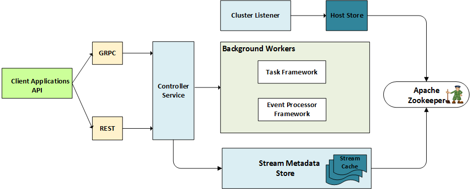
Controller Process Diagram
Components
Service Endpoints
There are two ports exposed by Controller: Client-Controller API and
Administration API. The client Controller communication is implemented as RPC which
exposes API to perform all Stream related control plane operations.
Apart from this Controller also exposes an administrative API implemented as REST.
Each endpoint performs the appropriate call to the Pravega Controller Service backend subsystem which has the actual implementation for various operations like create, read, update and delete (CRUD) on entities owned and managed by Controller.
gRPC
Client Controller communication endpoint is implemented as a gRPC
interface. Please check the complete list of API. This exposes API used by Pravega clients (Readers, Writers and Stream
Manager) and enables Stream management. Requests enabled by this API
include creating, modifying, and deleting Streams.
The underlying gRPC framework provides both synchronous and asynchronous programming models.
We use the asynchronous model in our client Controller interactions so that the client thread does not block on the response from the server.
To be able to append to and read data from Streams, Writers and Readers query Controller to get active Stream Segment sets, successor and predecessor Stream Segments while working with a Stream. For Transactions, the client uses specific API calls to request Controller to create, commit, abort and ping Transactions.
REST
For administration, the Controller implements and exposes a REST
interface. This includes API calls for Stream management as well as
other administration API primarily dealing with creation and deletion of
Scopes. We use swagger to describe our REST API. Please see, the swagger yaml file.
Pravega Controller Service 
This is the backend layer behind the Controller endpoints gRPC and
REST. All the business logic required to serve Controller API calls are
implemented here. This layer contains handles to all other subsystems like the various store implementations
(Stream store, Host store and Checkpoint store) and background processing frameworks (Task and Event Processor framework).
Stores are interfaces that provide access to various types of metadata managed by Controller. Background
processing frameworks are used to perform asynchronous processing that typically implements workflows involving metadata updates
and requests to Segment Store.
Stream Metadata Store
A Stream is a dynamically changing sequence of Stream Segments, where regions of the Routing Key space map to open Stream Segments. As the set of Segments of a Stream changes, so do the mapping of the Routing Key space to Segments.
A set of Segments is consistent iff the union of key space ranges mapping to Segments in the set covers the entire key space and the key space ranges are disjoint.
For example, suppose a set S = {S1, S2, S3}, such that:
- Region [0, 0.3) maps to Segment S1.
- Region [0.3, 0.6) maps to Segment S2.
- Region [0.6, 1.0) maps to Segment S3.
S is a consistent Segment set.
A Stream goes through transformations as it scales over time. A Stream starts with an initial set of Segments that is determined by the Stream configuration when created and it transitions to new sets of Segments as scale operations are performed on the Stream. Each generation of Segments that constitute the Stream at any given point in time are considered to belong to an epoch. A Stream starts with initial epoch 0 and upon each transition, it moves ahead in its epochs to describe the change in generation of Segments in the Stream.
The Controller maintains the Stream: it stores the information about all epochs that constitute a given Stream and also about their transitions. The metadata store is designed to persist the information pertaining to Stream Segments, and to enable queries over this information.
Apart from the epoch information, it keeps some additional metadata, such as state and its policies and ongoing Transactions on the Stream. Various sub-components of Controller access the stored metadata for each Stream via a well-defined interface. We currently have two concrete implementations of the Stream store interface: in-memory and Zookeeper backed stores. Both share a common base implementation that relies on Stream objects for providing store-type specific implementations for all Stream-specific metadata. The base implementation of Stream store creates and caches these Stream objects.
The Stream objects implement a store/Stream interface. The concrete Stream implementation is specific to the store type and is responsible for implementation of store specific methods. We have a common base implementation of all store types that provide optimistic concurrency. This base class encapsulates the logic for queries against Stream store for all concrete stores that support Compare And Swap (CAS). We currently use Zookeeper as our underlying store which also supports CAS. We store all Stream metadata in a hierarchical fashion under Stream specific znodes (ZooKeeper data nodes).
For the ZooKeeper-based store, we structure our metadata into different groups to support a variety of queries against this metadata. All Stream specific metadata is stored under a scoped/Stream root node. Queries against this metadata include, but not limited to, querying segment sets that form the Stream at different points in time, segment specific information, segment predecessors and successors. Refer to Stream metadata interface for details about API exposed by Stream metadata store.
Stream Metadata
Clients need information about what Segments constitute a Stream to start their processing and they obtain it from the epoch information the Controller stores in the stream store. Clients need the ability to query and find Stream Segments at any of the three cases efficiently:
- A Reader client typically starts from the head of the Stream,
- But it might also choose to access the Stream starting from any arbitrarily interesting position.
- Writers on the other hand always append to the tail of the Stream.
To enable such queries, the Stream store provides API calls to get the initial set of Stream Segments, Segments at a specific time and current set of Segments.
As mentioned earlier, a Stream can transition from one set of Stream Segments (epoch) to another set of Segments that constitute the Stream. A Stream moves from one epoch to another if there is at least one Stream Segment that is sealed and replaced by one or more set of Stream Segments that cover precisely the key space of the sealed Segments. As clients work on Streams, they may encounter the end of sealed Stream Segments and consequently need to find new Segments to be able to move forward. To enable the clients to query for the next Segments, the stream store exposes via the Controller Service efficient queries for finding immediate successors and predecessors for any arbitrary Segment.
To enable serving queries like those mentioned above, we need to efficiently store a time series of these Segment transitions and index them against time. We store this information about the current and historical state of a Stream Segments in a set of records which are designed to optimize on aforementioned queries. Apart from Segment-specific metadata record, the current state of Stream comprises of other metadata types that are described henceforth.
Records
Stream time series is stored as a series of records where each record corresponds to an epoch. As Stream scales and transitions from one epoch to another, a new record is created that has complete information about Stream Segments that forms the epoch.
-
Epoch Records:
Epoch: ⟨time, list-of-segments-in-epoch⟩. We store the series of active Stream Segments as they transition from one epoch to another into individual epoch records. Each epoch record corresponds to an epoch which captures a logically consistent (as defined earlier) set of Stream Segments that form the Stream and are valid through the lifespan of the epoch. The epoch record is stored against the epoch number. This record is optimized to answer to query Segments from an epoch with a single call into the store that also enables retrieval of all Stream Segment records in the epoch in O(1). This record is also used for fetching a Segment-specific record by first computing Stream Segment's creation epoch from Stream Segment ID and then retrieving the epoch record. -
Current Epoch: A special epoch record called
currentEpoch. This is the currently active epoch in the Stream. At any time exactly one epoch is marked as the current epoch. Typically this is the latest epoch with the highest epoch number. However, during an ongoing Stream update workflow like scale or rolling Transaction, the current epoch may not necessarily be the latest epoch. However, at the completion of these workflows, the current epoch is marked as the latest epoch in the stream. The following are three most commonly used scenarios where we want to efficiently know the set of Segments that form the Stream: - Initial set of Stream Segments: The head of the Stream computation is very efficient as it is typically either the first epoch record or the latest truncation record.
- Current set of Stream Segments: The tail of the Stream is identified by the current epoch record.
-
Successors of a particular Stream Segment: The successor query results in two calls into the store to retrieve Stream Segment's sealed epoch and the corresponding epoch record. The successors are computed as the Stream Segments that overlap with the given Stream Segment.
-
Segment Records: Segment-info: ⟨segmentid, time, keySpace-start, keySpace-end⟩. The Controller stores Stream Segment information within each epoch record. The Stream Segment ID is composed of two parts and is encoded as a 64 bit number. The high 32 bit identifies the creation epoch of the Stream Segment and the low 32 bit uniquely identifies the Stream Segment.
Note: To retrieve Stream Segment record given a Stream Segment ID, we first need to extract the creation epoch and then retrieve the Stream Segment record from the epoch record.
Stream Configuration
Znode under which Stream configuration is serialized and persisted. A Stream configuration contains Stream policies that need to be enforced. Scaling policy and Retention policy are supplied by the application at the time of Stream creation and enforced by Controller by monitoring the rate and size of data in the Stream.
-
The Scaling policy describes if and when to automatically scale is based on incoming traffic conditions into the Stream. The policy supports two flavors - traffic as the rate of Events per second and traffic as the rate of bytes per second. The application specifies their desired traffic rates into each segment by means of scaling policy and the supplied value is chosen to compute thresholds that determine when to scale a given Stream.
-
Retention Policy describes the amount of data that needs to be retained into Pravega cluster for this Stream. We support a time-based and a size-based retention policy where applications can choose whether they want to retain data in the Stream by size or by time by choosing the appropriate policy and supplying their desired values.
Stream State
Znode which captures the state of the Stream. It is an enumerator with values from creating, active, updating, scaling, truncating, sealing, and sealed. Once active, a Stream transition between performing a specific operation and remains active until it is sealed. A transition map is defined in the State class which allows and prohibits various state transitions. Stream State describes the current state of the Stream. It transitions from active to respective action based on the action being performed on the Stream. For example, during scaling the state of the Stream transitions from active to scaling and once scaling completes, it transitions back to active. Stream State is used as a barrier to ensure only one type of operation is being performed on a given Stream at any point in time. Only certain state transitions are allowed and are described in the state transition object. Only legitimate state transitions are allowed and any attempt for disallowed transition results in an appropriate exception.
Truncation Record
The Truncation Record captures the latest truncation point of the Stream which is identified by a StreamCut. The truncation StreamCut logically represents the head of the Stream and all the data before this position has been purged completely. For example, let there be n active Segments S1, S2, ...,Sn in a Stream. If we truncate this Stream at a StreamCut SC = {S1/O1, S2/O2,...,Sn/On}, then all data before the given StreamCut could be removed from the durable store. This translates to all the data in Segments that are predecessor Segments of Si for i ={ 1 to n }; and all the data in Segments Si till offset Oi. So we could delete all such predecessor Segments from the Stream and purge all the data before respective offsets from the Segments in StreamCut.
Sealed Segments Maps
Once the Stream Segments are sealed, the Controller needs to store additional information about the Stream Segment. Presently, we have two types of information:
- Epoch, the Stream Segment was sealed in.
- Size of the Stream Segment at the time of sealing.
These records have two different characteristics and are used in different types of queries. For example;
- Sealing epoch is important for querying successor Stream Segments. For each Stream Segment, we store its sealing epoch directly in the metadata store.
- Stream Segment sizes are used during truncation workflows. For sealed sizes, we store it in a map of Segment to size at the time of sealing.
- Successor queries are performed on a single Stream Segment whereas truncation workflows work on a group of Stream Segments.
This ensures that during truncation we are able to retrieve sealed sizes for multiple Stream Segments with a minimal number of calls into the underlying metadata store. Since we could have an arbitrarily large number of Stream Segments that have been sealed away, we cannot store all of the information in a single map and hence we shard the map and store it. The sharding function we use is to hash the creation epoch and get the shard number.
The following are the Transaction Related metadata records:
-
Active Transactions: Each new Transaction is created under the znode. This stores metadata corresponding to each Transaction as Active Transaction Record. Once a Transaction is completed, a new node is created under the global Completed Transaction znode and removed from under the Stream specific Active Transaction node.
-
Completed Transactions: All completed transactions for all Streams are moved under a separate znode upon completion (via either commit or abort paths). The completion status of Transaction is recorded under this record. To avoid proliferation of stale Transaction records, we provide a cluster level configuration to specify the duration for which a completed Transaction's record should be preserved. Controller periodically garbage collects all Transactions that were completed before the aforesaid configured duration.
Stream Store Caching
In-memory Cache
Since there could be multiple concurrent requests for a given Stream being processed by the same Controller instance, it is suboptimal to read the value by querying Zookeeper every time. So we have introduced an in-memory cache that each Stream store maintains. It caches retrieved metadata per Stream so that there is maximum one copy of the data per Stream in the cache. There are two in-memory caches:
- A cache of multiple Stream objects in the store
- Cache properties of a Stream in the Stream object.
The cache can contain both mutable and immutable values. Immutable values, by definition are not a problem. For mutable values, we have introduced a notion of Operation Context and for each new operation, which ensures that during an operation we lazily load latest value of entities into the cache and then use them for all computations within that Operation's context.
Operation Context
At the start of any new operation, we create a context for this operation. The creation of a new operation context invalidates all mutable cached entities for a Stream and each entity is lazily retrieved from the store whenever requested. If a value is updated during the course of the operation, it is again invalidated in the cache so that other concurrent read/update operations on the Stream get the new value for their subsequent steps.
Stream Buckets
To enable some scenarios, we may need the background workers to periodically work on each of the Streams in our cluster to perform some specific action on them. The concept of Stream Bucket is to distribute this periodic background work across all available Controller instances. Controller instances map all available streams in the system into buckets and these buckets are distributed amongst themselves. Hence, all the long-running background work can be uniformly distributed across multiple Controller instances.
Note: Number of buckets for a cluster is a fixed (configurable) value for the lifetime of a cluster.
Each bucket corresponds to a unique znode in
Zookeeper. A qualified scoped Stream name is used to compute a
hash value to assign the Stream to a bucket. All Controller instances, upon
startup, attempt to take ownership of buckets. Upon failover, ownerships
are transferred, as surviving nodes compete to acquire ownership of
orphaned buckets. The Controller instance which owns a bucket is
responsible for all long running scheduled background work corresponding
to all nodes under the bucket. Presently this entails running periodic
workflows to capture StreamCut(s) (called Retention-Set) for each Stream at desired frequencies.
Retention Set
One retention set per Stream is stored under the corresponding
bucket/Stream znode. As we compute StreamCut(s) periodically, we keep
preserving them under this znode. As some automatic truncation is
performed, the StreamCut(s) that are no longer valid are purged from
this set.
Controller Cluster Listener
Each node in Pravega Cluster registers itself under a cluster znode as an ephemeral node. This includes both Controller and Segment Store nodes. Each Controller instance registers a watch on the cluster znode to listen for cluster change notifications. These notify about the added and removed nodes.
One Controller instance assumes leadership amongst all Controller instances. This leader Controller instance is responsible for handling Segment Store node change notifications. Based on the changes in topology, Controller instance periodically rebalances segment containers to Segment Store node mapping.
All Controller instances listen for Controller node change notifications. Each Controller instance has multiple sub components that implement the failover sweeper interface. Presently there are three components that implement failover sweeper interface namely:
TaskSweeperEventProcessorsTransactionSweeper
Whenever a Controller instance is identified to have been removed from the cluster, the cluster listener invokes all registered failover sweepers to optimistically try to sweep all the orphaned work previously owned by the failed Controller host.
Host Store
The implementation of the Host store interface is used to store Segment Container to Segment Store
node mapping. It exposes API like getHostForSegment where it computes a
consistent hash of Segment ID to compute the owner Segment Container.
Then based on the container-host mapping, it returns the appropriate URI
to the caller.
Background Workers
Controller process has two different mechanisms or frameworks for processing background work. These background works typically entail multiple steps and updates to metadata under a specific metadata root entity and potential interactions with one or more Segment Stores.
We initially started with a simple task framework that gave us the ability to run tasks that take exclusive rights over a given resource (typically a Stream) and allowed for tasks to failover from one Controller instance to another. However, this model was limiting in scope and locking semantics, and had no inherent notion of task ordering as multiple tasks could race to acquire working rights (lock) on a resource concurrently. To overcome this limitation we came up with a new infrastructure called Event Processor. It is built using Pravega Streams and provides a clear mechanism to ensure mutually exclusive and ordered processing.
Task Framework
The Task Framework is designed to run exclusive background processing per resource such that in case of Controller instance failure, the work can easily failover to another Controller instance and brought to completion. The framework, on its own, does not guarantee idempotent processing and the author of a task has to handle it if required. The model of tasks is defined to work on a given resource exclusively, which means no other task can run concurrently on the same resource. This is implemented by way of a persisted distributed lock implemented on Zookeeper. The failover of a task is achieved by following a scheme of indexing the work a given process is performing. So if a process fails, another process will sweep all outstanding work and attempt to transfer ownership to itself.
Note that, upon failure of a Controller process, multiple surviving Controller processes can concurrently attempt sweeping of orphaned tasks. Each of them will index the task in their host-index but exactly one of them will be able to successfully acquire the lock on the resource and hence permission to process the task. The parameters for executing a task are serialized and stored under the resource.
Currently, we use the Task Framework only to create Stream tasks. All the other background processing is done using the Event Processor Framework.
Event Processor Framework
Event processors Framework is a background worker subsystem which reads Events from an internal Stream and processes it, hence the name Event Processor. In Pravega all Event Processors provides at least once processing guarantee. And in its basic flavor, the framework also provides strong ordering guarantees. The Event Processor framework on its own does not guarantee idempotent execution and it is the responsibility of the individual workflows implemented to ensure that the processing is idempotent and safe across multiple executions. In Pravega, there exist different subtypes of Event Processors which allow concurrent processing.
We create different Event Processors for different kinds of work. In Pravega, there are three different Event Processors:
- Committing Transaction,
- Aborting Transactions,
- Processing Stream specific requests (scale, update, seal, etc).
Each Controller instance has one Event Processor of each type. The Event Processor Framework allows for multiple Readers to be created per Event Processor. All Readers for a specific Event Processor across Controller instances share the same Reader Group, which guarantees mutually exclusive distribution of work across Controller instances. Each Reader gets a dedicated thread where it reads the Event, calls for its processing and upon completion of processing, updates its Checkpoint. Events are posted in the Event Processor-specific Stream and are routed to specific Stream Segments using scoped Stream name as the Routing Key.
Serial Event Processor
It essentially reads an Event and initiates its processing and waits on it to complete before moving on to the next Event. This provides strong ordering guarantees in processing. And it Checkpoints after processing each Event. Commit Transaction is implemented using this Serial Event Processor. The degree of parallelism for processing these Events is upper bounded by the number of Stream Segments in the internal Stream and lower bounded by the number of Readers. Multiple Events from across different Streams could land up in the same Stream Segment due to Serial processing. Serial processing has a drawback that, processing stalls or flooding of Events from one Stream could adversely impact latencies for unrelated Streams.
Concurrent Event Processor
To overcome the drawbacks of Serial Event Processor, in Pravega we designed Concurrent Event Processor. Concurrent Event Processor, as the name implies, allows us to process multiple Events concurrently. Here the Reader thread, reads an Event, schedules it’s asynchronous processing and returns to read the next event. There is a ceiling on the number of Events that are concurrently processed at any point in time and as the processing of some Event completes, newer Events are allowed to be fetched. The Checkpoint scheme here becomes slightly more involved to ensure the guarantee at least once processing.
However, with concurrent processing the ordering guarantees get broken. But, it is important to note that only ordering guarantees are needed for processing Events from a Stream and not across Streams. In order to satisfy ordering guarantee, we overlay Concurrent Event processor with Serialized Request Handler, which queues up Events from the same Stream in the in-memory queue and processes them in order.
-
Commit Transaction processing is implemented on a dedicated Serial Event Processor because strong commit ordering is required by ensuring that commit does not interfere with processing of other kinds of requests on the Stream.
-
Abort Transaction processing is implemented on a dedicated Concurrent Event Processor which performs abort processing on Transactions from across Streams concurrently.
All other requests for Streams are implemented on a Serialized Request Handler which ensures exactly one request per Stream is being processed at any given time and there is ordering guarantee within request processing. However, it allows for concurrent requests from across Streams to go on concurrently. Workflows like scale, truncation, seal, update and delete Stream are implemented for processing on the request Event Processor.
Roles and Responsibilities
Stream Operations
The Controller is the source of truth for all Stream related metadata.
Pravega clients (e.g., EventStreamReaders and EventStreamWriters), in
conjunction with the Controller, ensure that Stream invariants are
satisfied and honored as they work on Streams. The Controller maintains
the metadata of Streams, including the entire history of Stream Segments.
The Client accessing a Stream need to contact the Controller to obtain
information about Stream Segments.
Clients query Controller in order to know how to navigate Streams. For this purpose Controller exposes appropriate API to get active Stream Segments, successors, predecessors and URIs. These queries are served using metadata stored and accessed via Stream store interface.
The Controller also provides workflows to modify the state and behavior of the Stream. These workflows include create, scale, truncation, update, seal, and delete. These workflows are invoked both via direct API and in some cases as applicable via background policy manager (Auto Scaling and Retention).
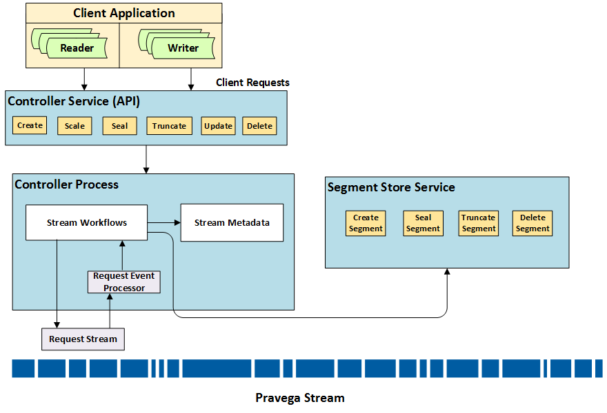
Request Processing Flow Diagram
Create Stream
The Create Stream is implemented as a task on Task Framework.
-
The Create Stream workflow first sets the initial Stream set to Creating.
-
Next, it identifies the Segment Containers that should create and own the new Segments for this Stream, and calls
CreateSegment()concurrently for all Segments. Once allCreateSegment()(s) return, thecreateStream()task completes its execution and change the Stream state to Active. In the case of recoverable failures, the operations are retried. -
However, if it is unable to complete any step, the Stream is left dangling in Creating state.
Update Stream
Update Stream is implemented as a task on Serialized Request Handler over Concurrent Event Processor Framework.
- Update Stream is invoked by an explicit API
updateStream()call into Controller. - It first posts an Update Request Event into request Stream.
- Following that it tries to create a temporary update property. If it fails to create the temporary update property, the request is failed and the caller is notified of the failure to update a Stream due to conflict with another ongoing update.
-
The Event is picked by Request Event Processor. When the processing starts, the update Stream task expects to find the temporary update Stream property to be present. If it does not find the property, the update processing is delayed by pushing Event the back in the in-memory queue until it deems the Event expired. If it finds the property to be updated during this period, before the expiry, the Event is processed and
updateStream()operation is performed. -
Once the update Stream processing starts, it first sets the Stream state to Updating.
- Then, the Stream configuration is updated in the metadata store followed by notifying Segment Stores for all active Stream Segments of the Stream, about the change in policy. Now the state is reset to Active.
Scale Stream
The Scale can be invoked either by explicit API call (referred to as manual scale) or performed automatically based on scale policy (referred to as Auto-scaling).
We first write the Event followed by updating the metadata store to capture our intent to scale a Stream. This step is idempotent and ensures that if an existing ongoing scale operation is in progress, then this attempt to start a new scale is ignored. Also, if there is an ongoing scale operation with a conflicting request input parameter, then the new request is rejected. Which essentially guarantees that there can be exactly one scale operation that can be performed at any given point in time.
The start of processing is similar to the mechanism followed in update Stream. If metadata is updated, the Event processes and proceeds with executing the task. If the metadata is not updated within the desired time frame, the Event is discarded.
- Once scale processing starts, it first sets the Stream State to Scaling.
-
Then creates new Stream Segments in Segment Store. The workflow is as follows:
- After successfully creating new segments, it creates a new epoch record in the metadata store.
- The created new epoch record corresponds to a new epoch which contains the list of Stream Segments as they would appear post scale.
- Each new epoch creation also creates a new root epoch node under which the metadata for all transactions from that epoch resides.
- After creating requisite metadata records, scale workflow attempts to seal the old Stream segments in the Segment Store.
-
After the old Stream Segments are sealed, we can safely mark the new epoch as the currently active epoch and reset state to Active.
Truncate Stream
Truncating a Stream follows a similar mechanism to update and has a temporary Stream property for truncation that is used to supply input for truncate Stream.
- Once the truncate workflow process starts, the Stream State is set to Truncating.
- Truncate workflow then looks at the requested
StreamCut, and checks if it is greater than or equal to the existing truncation point, only then is it a valid input for truncation and the workflow commences. - The truncation workflow takes the requested
StreamCutand computes all Stream Segments that are to be deleted as part of this truncation request. - Then calls into respective Segment Stores to delete identified Stream Segments. Post deletion, we call truncate on Stream Segments that are described in the
StreamCutat the offsets as described in theStreamcut. - Following this, the truncation record is updated with the new truncation point and deleted Stream Segments. The state is reset to Active.
Seal Stream
Seal Stream can be requested via an explicit API call into Controller. It first posts a seal Stream Event into request Stream.
- Once the Seal Stream process starts, the Stream State is set to Sealing.
- If the event is picked and does not find the Stream to be in the desired state, it postpones the seal Stream processing by reposting it at the back of in-memory queue.
- Once the Stream is set to sealing state, all active Stream Segments for the Stream are sealed by calling into Segment Store.
- After this, the Stream is marked as Sealed in the Stream metadata.
Delete Stream
Delete Stream can be requested via an explicit API call into Controller. The request first verifies if the Stream is in Sealed state. - Only sealed Streams can be deleted and an event to this effect is posted in the request Stream. - When the event is picked for processing, it verifies the Stream state again and then proceeds to delete all Stream Segments that belong to this Stream from its inception by calling into Segment Store. - Once all Stream Segments are deleted successfully, the Stream metadata corresponding to this Stream is cleaned up.
Stream Policy Manager
As described earlier, there are two types of user-defined policies that Controller is responsible for enforcing, namely Automatic Scaling and Automatic Retention. The Controller is not just the store for Stream policy but it actively enforces those user-defined policies for their Streams.
Scaling Infrastructure
Scaling infrastructure is built in conjunction with Segment Stores. As the Controller creates new Stream Segments in Segment Stores, it passes user-defined scaling policies to Segment Stores. The Segment Store then monitors traffic for the said Stream Segment and reports to Controller if some thresholds, as determined from policy, are breached. The Controller receives these notifications via Events posted in dedicated internal Streams. There are two types of traffic reports that can be received for segments.
- It identifies if a Stream Segment should be scaled up (Split).
- It identifies if a Stream Segment should be scaled down (Merge).
For Stream Segments eligible for scale up, the Controller immediately posts the request for Stream Segment scale up in the request Stream for Request Event Processor to process. However, for scale down, the Controller needs to wait for at least two neighboring Stream Segments to become eligible for scale down. For this purpose, it marks the Stream Segment as cold in the metadata store. The Controller consolidates the neighboring Stream Segments that are marked as cold and posts a scale down the request for them. The scale requests processing is then performed asynchronously on the Request Event Processor.
Retention Infrastructure
The retention policy defines how much data should be retained for a
given Stream. This can be defined as time-based or size-based. To apply
this policy, Controller periodically collects StreamCut(s) for the Stream
and opportunistically performs truncation on previously collected StreamCut(s) if policy dictates it. Since this is a periodic background work that needs to be performed for all Streams that have a retention policy defined, there is an imperative need to fairly distribute this workload
across all available Controller instances. To achieve this we rely on
bucketing Streams into predefined sets and distributing these sets
across Controller instances. This is done by using Zookeeper to store
this distribution. Each Controller instance, during bootstrap, attempts
to acquire ownership of buckets. All Streams under a bucket are
monitored for retention opportunities by the owning Controller. At each
period, Controller collects a new StreamCut and adds it to a
retention set for the said Stream. Post this it looks for the candidate
StreamCut(s) stored in retention set which are eligible for truncation
based on the defined retention policy. For example, in time-based
retention, the latest StreamCut older than the specified retention period
is chosen as the truncation point.
Transaction Manager
Another important role played by the Controller is that of the Transaction manager. It is responsible for the beginning and ending Transactions. The Controller plays an active role in providing guarantees for Transactions from the time they are created until the time they are committed or aborted. The Controller tracks each Transaction for their specified timeouts, and automatically aborts the Transaction if the timeout exceeds. The Controller is responsible for ensuring that the Transaction and a potential concurrent scale operation play well with each other and ensure all promises made with respect to either are honored and enforced.
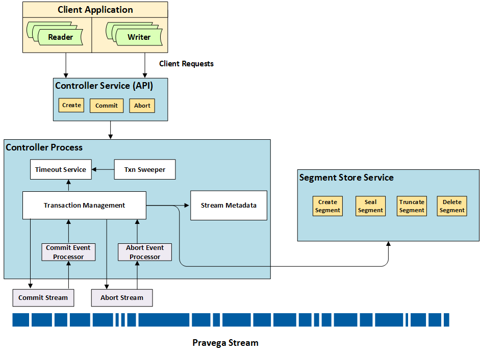
Transaction Management Diagram
Client calls into Controller process to create, ping commit or abort transactions. Each of these requests is received on Controller and handled by the Transaction Management module which implements the business logic for processing each request.
Create Transaction
Writers interact with Controller to create new Transactions. Controller Service passes the create transaction request to Transaction Management module.
The create Transaction function in the module performs the following steps:
- Generates a unique UUID for the Transaction.
- It fetches the current active set of Stream Segments for the Stream from metadata store and its corresponding epoch identifier from the history.
- It creates a new Transaction record in the Zookeeper using the metadata store interface.
- It then requests Segment Store to create special Transaction Segments that are inherently linked to the parent active Stream Segments.
The Controller creates shadow Stream Segments for current active Segments by associating Transaction ID to compute unique shadow Stream Segment identifiers. The lifecycle of shadow Stream Segments are not linked to original Stream Segments and original Stream Segments can be sealed, truncated or deleted without affecting the lifecycle of shadow Stream Segment.
Commit Transaction
Upon receiving the request to commit a Transaction, Controller Service passes the request to Transaction Management module. This module first tries to mark the Transaction for commit in the Transaction specific metadata record via metadata store.
Following this, it posts a commit Event in the internal Commit Stream. The commit event only captures the epoch in which the Transaction has to be committed. Commit Transaction workflow is implemented on commit Event processor and thereby processed asynchronously.
- When commit workflow starts, it opportunistically collects all available Transactions that have been marked for commit in the given epoch and proceeds to commit them in order and one Transaction at a time.
- A Transaction commit entails merging the Transaction Segment into its parent Segment. This works perfectly in absence of scale.
- However, because of scaling of a Stream, some of the parent Segments for Transaction's shadow Stream Segments could have been sealed away.
- In such instance, when we attempt to commit a Transactions we may not have parent Segments in which Transaction Segments could be merged into.
- One approach to mitigate this could have been to prevent scaling operation while there were ongoing Transactions. However, this could stall scaling for an arbitrarily large period of time and would be detrimental. Instead, controller decouples scale and Transactions and allows either to occur concurrently without impacting workings of the other. This is achieved by using a scheme called Rolling Transactions.
Rolling Transactions
This is achieved by using a scheme (Rolling Transactions) where controller allows Transaction Segments to outlive their parent Segments and whenever their commits are issued, at a logical level controller elevates the Transaction Segments as first class Segments and includes them in a new epoch in the epoch time series of the Stream.
- Transactions are created in an older epoch and when they are attempted to be committed, the latest epoch is sealed, Transactions are rolled over and included and then a duplicate of the latest epoch is created for Stream to restore its previous state before rolling of Transactions.
- This ensures that Transactions could be created at any time and then be committed at any time without interfering with any other Stream processing.
- The commit workflow on the controller guarantees that once started it will attempt to commit each of the identified Transactions with indefinite retries until they all succeed.
- Once a Transaction is committed successfully, the record for the Transaction is removed from under its epoch root.
Abort Transaction
Abort, like commit, can be requested explicitly by the application. However, abort can also be initiated automatically if the Transaction’s timeout elapses.
- The Controller tracks the timeout for each and every Transaction in the system and whenever timeout elapses, or upon explicit user request, Transaction Management module marks the Transaction for abort in its respective metadata.
- After this, the Event is picked for processing by abort Event Processor and the Transactions abort is immediately attempted.
- There is no ordering requirement for abort Transaction and hence it is performed concurrently and across Streams.
Ping Transaction
Since Controller has no visibility into data path with respect to data being written to segments in a Transaction, Controller is unaware if a Transaction is being actively worked upon or not and if the timeout elapses it may attempt to abort the Transaction. To enable applications to control the destiny of a Transaction, Controller exposes an API to allow applications to renew Transaction timeout period. This mechanism is called ping and whenever application pings a Transaction, Controller resets its timer for respective transaction.
Transaction Timeout Management
Controllers track each Transaction for their timeouts. This is implemented as timer wheel service. Each Transaction, upon creation gets registered into the timer service on the Controller where it is created. Subsequent pings for the Transaction could be received on different Controller instances and timer management is transferred to the latest Controller instance based on ownership mechanism implemented via Zookeeper. Upon timeout expiry, an automatic abort is attempted and if it is able to successfully set Transaction status to abort, the abort workflow is initiated.
Each Transaction that a Controller is monitoring for timeouts is added to this processes index. If such a Controller instance fails or crashes, other Controller instances will receive node failed notification and attempt to sweep all outstanding Transactions from the failed instance and monitor their timeouts from that point onward.
Segment Container to Host Mapping
The Controller is also responsible for the assignment of Segment Containers to Segment Store nodes. The responsibility of maintaining this mapping befalls a single Controller instance that is chosen via a leader election using Zookeeper. This leader Controller monitors lifecycle of Segment Store nodes as they are added to/removed from the cluster and performs redistribution of Segment Containers across available Segment Store nodes. This distribution mapping is stored in a dedicated znode. Each Segment Store periodically polls this znode to look for changes and if changes are found, it shuts down and relinquishes containers it no longer owns and attempts to acquire ownership of containers that are assigned to it.
The details about implementation, especially with respect to how the metadata is stored and managed is already discussed in the section Cluster Listener.